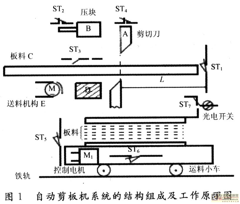
1 Design System Requirements The structure and working principle of the automatic shearing machine system are shown in Fig. 1. The system can cut large plates according to requirements and transport them to the packing line or individual material points by a feeding trolley. When it is not in operation, the limit switches ST2, ST3 and ST4 of the pressure block and the shearing blade are both disconnected, and both the limit switch ST1 and the photoelectric proximity switch ST7 are also disconnected. The shearing knife, the briquetting block, and the material selection mechanism are respectively driven by the AC motor, and the material transportation vehicle is driven by the DC control motor. The working process is as follows:
(1) Read the status of the limit switch ST6 and judge whether the trolley is unloaded. If it is unloaded, it can start working.
(2) Start the feeding trolley and put it into place. At this time, the limit switch ST5 is closed.
(3) When the SSRe is energized, the feeding mechanism E is started to move the sheet material to the right.
(4) When the sheet hits the stroke switch ST1, the feeding is stopped, and at the same time, the SSRb power-on starts the depressing mechanism, the pressing block B is pressed down, and the block upper limit switch ST2 is reset and closed.
(5) When the compact is in place and the material is pressed, the compact lower limit switch ST3 is closed.
(6) When the SSRe is energized, the shearing knife mechanism is started to control the shears of the shear. The ST4 is reset and closed until the sheet is cut. When the sheet falls past the photoelectric proximity switch ST7, ST6 outputs a pulse and increments the 8031 ​​counter.
(7) It is judged whether the number of sheets on the trolley is enough, and if not, the steps (3) to (7) after the start of the feeding mechanism are continuously repeated. Once the number is sufficient, the control motor is energized, the control motor of the transport trolley is rotating forward, the trolley is on the right, and the cut sheet is sent to the packaging line or the respective material points. After the sheet is unloaded, the cart is re-inverted and returned to the shearer, where it begins the shear loading of the next vehicle.
The length L of the sheet can be freely adjusted as required. The number of sheets per car (bundle) can be given by the machine keyboard or can be set by dialing the keyboard. The counts of sheets fixed to the packing line or sent to the respective material points can be arbitrarily changed and completed by a software system.
2 hardware system design Using the 8031 ​​single-chip microcomputer to achieve automatic cutting machine production process control hardware design circuit shown in Figure 2.

The system is mainly composed of a single chip 8031, a 2716 readable and writable memory, 7 switches (ST1~ST7) input, 3 solid state relay control interfaces, and a motor bidirectional control interface; in addition, there is a counter for shearing. The cut sheet is counted. In Figure 2, 74LS273-1# is the address latch, 8031 ​​internal timer/counter 0 is used as the material counter; 74LS273-2# is the I/O expansion interface, its address is 7FFFH. Here, 1D to 6D are used as digital input bits, and they are connected to ST1 to ST6 respectively. The two bits of P1.0 and P1.1 are used as bidirectional motors (reversible DC motor M1) to control the forward or backward movement of the trolley. The P1.2 to P1.4 and P3 ports of the P1 port are used to control the AC drive motors of the shears, briquetting blocks, and feed mechanisms to perform operations such as shearing, pressing, and automatic feeding. In order to improve the system's anti-jamming capability, the design of the hardware system is simple and it adopts full floating technology, that is, each input terminal of the switch has an optical isolator, and the control output adopts a photoelectric isolation solid relay.
2.1 Switch Input Interface Circuit The digital input interface circuit uses an opto-isolator, as shown in Figure 3. In the figure, when the control switch ST1 is off, the light-emitting diode has no current through it, so the phototransistor is turned off and the output is high (“1â€); once the ST1 is closed, the light-emitting diode is turned on, causing the phototransistor to turn on and the output is low Level ("0").

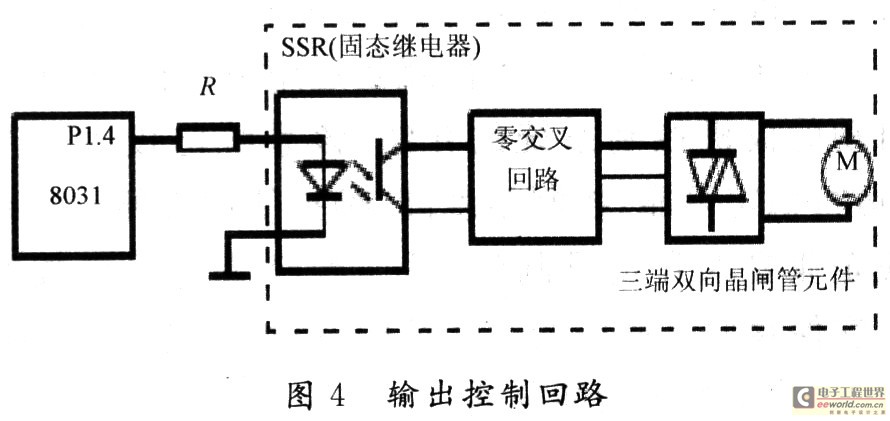
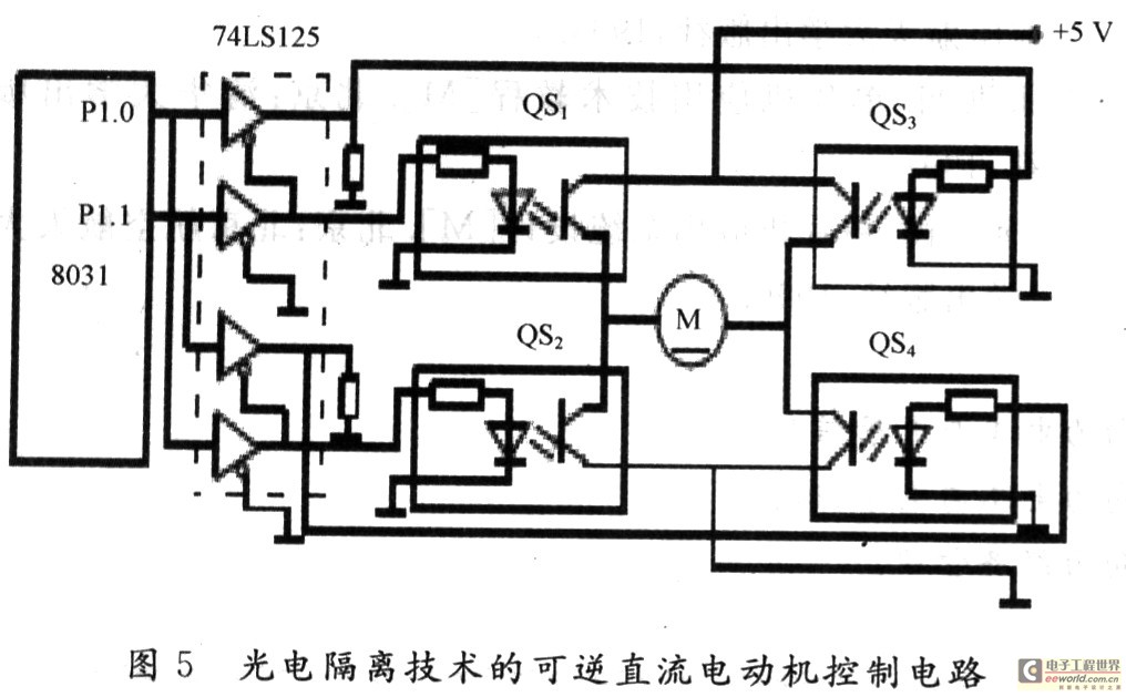
2.2 Output Control Circuit The output control circuit adopts solid state relay SSR. Its interface circuit is shown in Figure 4. The input is TTL level and the output is AC load. When the P1.4 terminal outputs a high level "1", the solid state relay SSR is turned on and the AC motor is powered on. Conversely, if the P1.4 terminal outputs a low level ("0"), the SSR is cut off and the AC motor is also turned off. Followed by power outages. The other two are exactly the same. In order to achieve the purpose of photoelectric isolation, four DC solid state relays QS1 to QS4 form a reversible DC motor control circuit (ie, a bidirectional servo motor control circuit), as shown in FIG. 4 .
The truth table for reversible DC motor control (ie, bidirectional motor control) is shown in Table 1.

It is worth noting that: the system does not necessarily have to use optical isolation technology or solid state relays, it can also design a simple circuit. Full float technology is used here, mainly to provide the reader with a more comprehensive understanding of the full floating microcontroller control system.
3 software design Automatic shears production process control software using a modular structure, sequence control system program design can be based on the flow chart, you can also write a program table for each step, or draw a logical function diagram. The control program is divided into two parts, one part is the main program, which is used to initialize the system, ie set the interrupt control word and counting constants; the other part is the interrupt service program, which controls the production process of the shearer system.
Because this system is a sequential control system, it belongs to the time-sharing control, and the real-time performance is not high. Therefore, the program inquiry-type control method is used. In the control of the electromechanical acceleration and deceleration motion control subroutine design, in order to ensure that the control electromechanical does not lose step or overshoot in the frequent start-stop operation, to ensure the accuracy and rapidity of the system, according to the principle of rigid body rotation theory of mechanical principles, with reference to the characteristics of the control motor, Combined with load test conditions.
3.1 Main program The main program is used to initialize the system, ie set the interrupt control word and counting constants. After the main program is executed, it enters the waiting state. When the system needs to work, as long as the operator clicks the Start button, you can go to the appropriate interrupt service routine.
The main program flow chart shown in Figure 6.
The main program is as follows:

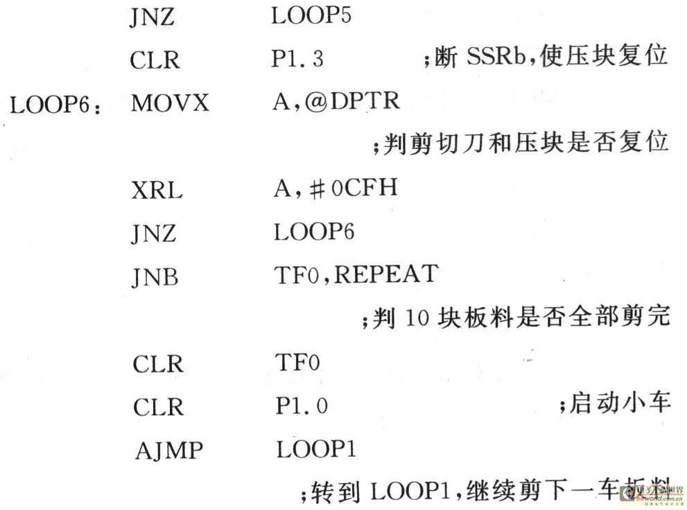
3.2 Interrupt Service Routine The interrupt service routine is used to control the system. The interrupt service routine flow chart is shown in Figure 7.

The interrupt service routine is as follows:

4 Conclusion This system is a sequential control system designed using 8031 ​​microcontroller, hardware circuit, interface is simple, software development and debugging are more convenient, in the input and output side using optical isolation and other measures, the anti-interference effect is very good. After the practical application of automatic transformation of several different types of shearing machine tools, this system fully embodies the characteristics of high integration, high processing precision, good economy, easy operation, high level of automation, and reliability of the equipment. Both maintenance and flexibility are excellent, basically meeting the needs of modern and large-scale production of electromechanical equipment factories.
Polyurethane Tufflex Screen,Urethane Screen Panels,Polyurethane Dewatering Screen,Polyurethane Screen Media
Anping Red Star Wire Mesh MFG Co., Ltd. , https://www.screening-media.net