1 V cone flowmeter and its working principle
The inner cone flowmeter originates from McCrometer of USA, because its throttling part is conical, the English name is V-Cone Flowmeter; After introducing the country, it is called the inner cone flowmeter (see Figure 1).
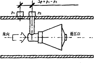
Fig.1 Schematic diagram of inner cone throttling device
The V-cone flowmeter and the orifice flowmeter are both differential pressure flowmeters. Its main theoretical basis is the law of conservation of energy and the continuity equation of flow in a closed pipe, ie the Bernoulli theorem. The content of the theorem is that in a constant-flow pipe section, the pressure of the fluid is inversely proportional to the square of the fluid velocity in the pipe section.
As shown in Fig. 1, the pressure of the fluid near the inner cone throttle is p1. Take this pressure as the reference static pressure at the reference flow rate; when the fluid flows through the inner cone throttle area, the cross-sectional area of ​​the pipeline becomes smaller. The flow rate is increased to maintain the energy constant, and the pressure is minimized at the pressure tap at the end of the cone, where the pressure is taken as the flow rate variation p2. Measure the pressure difference between these two places  According to Bernoulli’s theorem,
  The flow rate can be calculated.
2 V Cone Flowmeter Selection Calculation
The selection calculation of the throttling device and the unit conversion involved are very tedious and will not be repeated here. The following is only quoted by the national standard (GB/T2624-93) equation calculation of the inner cone flowmeter selection. The letter code in the formula is described in Table 1. For the sake of comparison, both formulae are based on the International System of Units and undergo formal processing.
International orifice flow formula:


Standard V cone flow formula:


It can be seen that Y in the inner cone formula is in the national standard formula.  CD is equivalent to C. It can be seen that they are exactly the same.
However, first of all, here we must pay attention to a substantial difference: the same is the throttling device, the orifice is the external measurement of the throttling, the internal cone is the central conical throttling. Therefore, the concept of "throttle ratio" is used to describe the throttling degree of a throttling device: it is equal to the square root of the ratio of the minimum flow area of ​​the throttling device at the throttling point to the internal cross-sectional area of ​​the throttling device, and is also counted as  . This is more than
  The diameter is called more accurate than physical. For orifice plate throttling devices, there are:

For the V cone throttling device, there are:

= 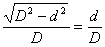
In the formula: d' is the equivalent open circle diameter of the inner cone throttling device.
Second, the formula for the coefficient of expansion is also somewhat different. Regardless of the national standard  To indicate this, the American Gas Association uses Y to indicate that they are:
 (or Y) = 1 - (0.41 + 0.35
The formula for the expansion coefficient of the standard V cone is
Y=1-(0.649+0.696  )
) 
Finally, and most importantly, the issue of the evaluation of the outflow coefficient. For standard orifice throttling devices, the national standard gives:
C=0.5959+0.0312 
For the V cone throttling device, McCrometer Corporation publicly gives an estimate:
CD=1-(1- 
From the formula, it can be clearly seen that the CD here is irrelevant to the Reynolds number, which is only based on the geometry of the throttling device; and the difference between the CD estimate and the actual value obtained from this formula is indicated as  , the applicable condition is 0.4<
  <0.85, 0.025m
In fact, the inner cone throttling device, like other throttling devices, obeys similar laws, which means that the inner cone flowmeter can also perform reference calculations just like standard orifice plates. For example, iterative method, according to the McCrometer company's corporate standard is to determine the initial value of a CD using the above formula of the outflow coefficient, and then calculate the Reynolds number through the flow formula and Reynolds number formula, and then find the corresponding new CD from the ReD-CD table. The value is repeated iteratively until the absolute value of the difference between the last two flow calculations is less than 0.01%.
However, V-cone flowmeters currently have problems of protection of intellectual property rights and market interests. Manufacturers do not provide ReD-CD tables, which is inconvenient. After analysis of some technical data and experimental data, this paper proposes adding a Reynolds number correction term to the formula for estimating the outflow coefficient to derive the following formula to replace the ReD-CD table for iterative calculation:
CD=1-  The selection calculation like this can fully meet the requirements for the preparation of engineering proposals, the determination of the flowmeter path and the length of the straight pipe, and the calculated CD value can also be used for calculations below the second level, but this is only an estimate.
For the calculation of the remaining parameters, the two formulae are exactly the same, including the conversion of the standard state and working state of the gas volume, the Reynolds number, and the thermal expansion of the material.
The letter code meanings in the formula are listed in Table 1.
Table 1 letter code meaning
C outflow coefficient (national standard nomenclature)
 Fluid density under operating conditions, kg/m3
CD outflow coefficient (inner cone nomenclature)
p hydrostatic pressure, pa
D orifice diameter or inner cone outer diameter under D conditions, m
 Differential pressure, Pa
D flowmeter diameter, D
 Isentropic index
 Turbine ratio coefficient under working conditions
Y expansibility coefficient
 Expansion coefficient
Qm mass flow, kg/s
3 The characteristics of the inner cone flowmeter
The V-cone flowmeter has more advantages and wider application fields than the standard orifice flowmeter. From McCrometer's technical data in the United States, you can access a large number of reports and records of experiments, standard organization verifications, and industrial applications. This article only lists some data of the verification results of five sample tables in the development process of the internal cone flowmeter of China's Yinhe Instrument Co., Ltd. in Table 2. The verification was completed by the Measurement Center of the 11th Institute of China Aerospace Corporation. These data and data are undoubtedly the best explanation of the following indicators and characteristics.
3.1 Measurement accuracy
If the error of the pressure sensing instrument and the secondary instrument is not taken into consideration, the internal cone flowmeter, like the standard orifice flowmeter, can have an uncertainty of ±0.5%, which is in accordance with the requirements of the national standard for gas commercial measurement.
3.2 Repeatability
The repeatability of the V-cone flowmeter is less than ±0.1%. Even at low Reynolds number non-linear segments, measurement repeatability is very good. This means that data processing technology can be used to further extend the measurement range of the flow meter. The reproducibility of standard orifices is included in the uncertainty, not just list.
3.3 Range ratio
The typical single-table turndown ratio for a V-cone flowmeter is 10:1. This indicator is much wider than the 3:1 of standard orifice flowmeters. From Table 2, it can be seen that it can also achieve a higher turndown ratio.
Table 2 Galactic cone flowmeter verification results
Calculation formula
Q=A+B 
D/mm
50.000
50.000
50.000
100.000
200.00

0.452
0.650
0.854
0.850
A
0.05994628
-0.01709265
-0.01640338
0.75247742
1.05969451
B
1.71625861
4.04465749
8.60156801
15.08579841
59.88791366
Flow/differential pressure


2.351
1.787
0.544
0.019
3.320
0.151
6.397
0.141
19.914
0.104
3.336
3.634
2.010
0.250
11.567
1.810
18.060
1.325
67.677
1.222
Measurements
4.428
6.501
6.976
2.988
19.439
5.098
35.172
5.223
123.031
4.092
5.471
9.942
11.122
7.603
27.437
10.177
47.587
9.553
173.453
8.325
6.593
14.502
14.679
15.063
33.315
15.073
61.366
16.160
233.034
15.078
uncertainty
0.30%
0.27%
0.32%
0.47%
0.57%
Accuracy level
0.5
0.5
0.5
0.5
1.0
Range ratio
2.8:1
28.8:1
10:1
9.6:1
11.7:1
3.4 Throttling ratio  (diameter ratio)
Standard cone device  Values ​​range from 0.45 to 0.85. Standard orifice device
  Values ​​range from 0.20 to 0.75. Inner cone device
  The value is not dominant at the low end, because the inner cone is throttled in the center of the pipe, and in the same gap condition, the surrounding effective area is larger than the center. For example, when
  At 0.45, the d/D in the orifice plate assembly is 0.45; however, the d/D in the cone device is equal to 0.893. Even smaller than this gap will produce wave interference. However, from another aspect of this indicator, it is clear that the flowmeter with the same diameter of the flowmeter and the inner cone throttling device has a large circulation capacity of 28.4%, and this advantage is pursued in engineering.
3.5 Reynolds number Re
The V-cone device has a Reynolds number range of 5 x 10³ to 1 x 10⁷. For orifice plate devices with angled pressure, when 0.20 ≤  When ≤ 0.45, ReD≥5×10³ is required;
  > 0.45, ReD ≥ 1×10⁴ For orifice plate devices with flange pressure requirements, ReD ≥ 1.26×10⁶
  2D; for comparison with the inner cone device, take
  = 0.45, D = 0.100m, then ReD ≥ 2.55 × 10⁴. Obviously, the inner cone device has a wider working range at the low end of the Reynolds number, which also explains why the inner cone flowmeter has a wider application range and a wider range, especially when the medium viscosity is large, resulting in a low Reynolds number. Time.
At the high end of the Reynolds number, although orifice devices can reach infinity, for general factory metering applications, 1  It is enough. The specification limits the maximum flow rate of the medium in the pipeline and rarely exceeds this value.
3.6 Pressure loss
Because the inner cone device does not use the throttling of the facade at right angles to the flow direction, the loss of positive impact is avoided, so the permanent pressure loss caused is naturally small. In addition, the influence of the signal noise of the inner cone device is very small (see 3.10), and the allowable lower limit value of the differential pressure can be lower, which is also one of the design strategies for reducing the pressure loss. From the inner cone and orifice pressure loss formula and its curve (as shown in Figure 2), we can quantitatively conclude that the pressure loss of the inner cone is smaller, but the difference is not significant.
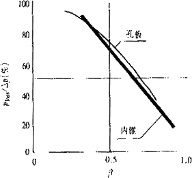
Figure 2 Throttling ratio coefficient - pressure loss curve
Orifice pressure loss formula: 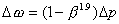
Cone pressure loss formula: 
PP PP is a hollow ball material injection molding, mold our independent research and development, efficient and practical.Pp packing is the exhaust gas Purification Tower in will be used for packing, generally placed in the tower in the mist purification device layer or washing layer.Mainly from the filter, neutralization and water mist in the role of the company's own production of PP hollow spheres, spherical shape, there are 12 leaves. A large number of production, cheap and good quality.
PP Filling,Mini PP Filling,Plastic PP Filling
Shenzhen Xicheng Plastic Co., Ltd. , http://www.china-xicheng.com